

Avanti: Componenti analogiche di bassa frequenza
Su: Rappresentazione dei segnali modulati
Indietro: Rappresentazione dei segnali modulati
Indice
Indice analitico
Introduciamo l'argomento ricordando come un segnale
x t
t = acos
 t +
t + 
 possa essere rappresentato per mezzo del fasore
 = aej
= aej ,
mediante la relazione
x
 t
t =
= 

 ej
ej t
t .
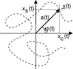
Estendiamo ora il concetto, definendo l'inviluppo complesso

 t
t come un fasore per il quale il modulo a e la fase
  siano
funzioni del tempo
rappresentato nella figura a fianco assieme ad una sua potenziale traiettoria
temporale. Ad

 t
t possiamo associare un segnale
reale
corrispondente ad imprimere al piano dell'inviluppo complesso una rotazione
antioraria a velocità angolare
 .
.
L'inviluppo complesso è un potente strumento che permette di descrivere il processo
di modulazione in modo semplice ed omogeneo. Ad esempio, il caso (già noto)
di traslazione in frequenza del segnale
a t
t mediante moltiplicazione
per un coseno, corrisponde ad un inviluppo complesso

 t
t = a
= a t
t a fase nulla: ad esso si dà il nome di modulazione di ampiezza8.8 per (l'evidente) ragione che l'ampiezza del coseno varia in funzione del segnale
a
 t
t ; la frequenza
f0 =
  prende il nome di frequenza portante. Se al contrario consideriamo un
inviluppo complesso con modulo costante

 t
t = ej
= ej
 t
t ,
l'andamento della fase

 t
t imprime alla portante
non modulata un diverso tipo di modulazione, detto modulazione di fase8.9 o angolare in quanto il segnale modulante (

 t
t in questo caso) altera l'argomento del coseno.
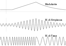
Prima di proseguire, riflettiamo sul risultato mostrato in figura, in cui si
considera un segnale modulante
m t
t prima costante, poi
a rampa lineare, e quindi decrescente. Ponendo

 t
t = m
= m t
t si ottiene una portante modulata in ampiezza, mentre con

 t
t = ejm
= ejm t
t la portante modulata angolarmente
x
 t
t = cos
= cos 2
2 f0t + m
 t
t
 presenta una ampiezza costante, ed una frequenza che nell'intervallo in cui
m
 t
t aumenta linearmente cambia in un valore più elevato,
per poi diminuire. In pratica, se
m
 t
t =
=  t, allora
l'argomento del coseno diviene
2
 f0t +
f0t +  t = 2
t = 2
 f0 +
f0 + 
 t.
t.
Per meglio descrivere il caso di modulazione angolare, definiamo una fase
istantanea
ed una frequenza istantanea
In questi termini, la modulazione angolare viene distinta in modulazione
di fase propriamente detta quando
mentre viene detta modulazione di frequenza quando
in quanto in questo caso è la frequenza istantanea a dipendere direttamente
dal segnale modulante:
fi t
t = f0 + kfm
 t
t .
.


Avanti: Componenti analogiche di bassa frequenza
Su: Rappresentazione dei segnali modulati
Indietro: Rappresentazione dei segnali modulati
Indice
Indice analitico
alef@infocom.uniroma1.it
2001-06-01


![]() t
t![]() mediante moltiplicazione
per un coseno, corrisponde ad un inviluppo complesso
mediante moltiplicazione
per un coseno, corrisponde ad un inviluppo complesso
![]()
![]() t
t![]() = a
= a![]() t
t![]() a fase nulla: ad esso si dà il nome di modulazione di ampiezza8.8 per (l'evidente) ragione che l'ampiezza del coseno varia in funzione del segnale
a
a fase nulla: ad esso si dà il nome di modulazione di ampiezza8.8 per (l'evidente) ragione che l'ampiezza del coseno varia in funzione del segnale
a![]() t
t![]() ; la frequenza
f0 =
; la frequenza
f0 = ![]() prende il nome di frequenza portante. Se al contrario consideriamo un
inviluppo complesso con modulo costante
prende il nome di frequenza portante. Se al contrario consideriamo un
inviluppo complesso con modulo costante
![]()
![]() t
t![]() = ej
= ej![]()
![]() t
t![]() ,
l'andamento della fase
,
l'andamento della fase
![]()
![]() t
t![]() imprime alla portante
non modulata un diverso tipo di modulazione, detto modulazione di fase8.9 o angolare in quanto il segnale modulante (
imprime alla portante
non modulata un diverso tipo di modulazione, detto modulazione di fase8.9 o angolare in quanto il segnale modulante (
![]()
![]() t
t![]() in questo caso) altera l'argomento del coseno.
in questo caso) altera l'argomento del coseno.
