

Avanti: Rapporto segnale rumore dei generatori
Su: Rumore Termico
Indietro: Rumore Termico
Indice
Indice analitico
Ai capi di un resistore R a temperatura T è presente una tensione
a vuoto
n t
t , realizzazione di un processo gaussiano a
media nulla, che è l'effetto del moto caotico degli elettroni all'interno della
resistenza14.1. Lo spettro di densità di potenza della tensione a vuoto ha espressione
in cui
k = 1.38 . 10-23 joule/oK è la costante di Boltzman
ed
 = 6.62 . 10-34 Joule . sec è la costante di Plank:
questi valori fanno sì che l'approssimazione
 n
n f
f
 2kTR
sia valida ad ogni frequenza di interesse.
In un bipolo passivo di impedenza
Z f
f = R
= R f
f + jX
+ jX f
f ,
solamente la parte reale (componente resistiva) concorre a generare il processo
di rumore termico, che pertanto possiede una densità di potenza
 n
n f
f
 2KTR
2KTR f
f .
Nel caso in cui il bipolo contenga più resistori a temperature diverse,
si può definire una temperatura equivalente
Te
 f
f ; un
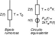
bipolo passivo equivale pertanto allo stesso bipolo non rumoroso (a temperatura
zero), con in serie un generatore di rumore con densità di potenza
 n
n f
f
 2kTe
2kTe f
f R
R f
f .
Questo generatore equivalente, è quindi descritto da una potenza disponibile
di rumore
Nel caso in cui
Te
 f
f = T0 = 290 oK (temperatura
ambiente), il termine
kT0 = 2
 dn
dn f
f assume
i valori riportati di seguito per diverse unità di misura, da adottare in alternativa,
allo scopo di rendere la grandezza omogenea con le altre che compaiono nelle
formule di progetto:
| kT0 |
= |
-204 [dBW/Hz] |
= |
-174 [dBm/Hz] |
= |
-114 [dBm/MHz] |
<><>
Ad esempio, all'uscita di un filtro passa-banda ideale non rumoroso di estensione
1 MHz, si ha una potenza disponibile di rumore pari a
10-11.4 mW .


Avanti: Rapporto segnale rumore dei generatori
Su: Rumore Termico
Indietro: Rumore Termico
Indice
Indice analitico
alef@infocom.uniroma1.it
2001-06-01
![]() t
t![]() , realizzazione di un processo gaussiano a
media nulla, che è l'effetto del moto caotico degli elettroni all'interno della
resistenza14.1. Lo spettro di densità di potenza della tensione a vuoto ha espressione
, realizzazione di un processo gaussiano a
media nulla, che è l'effetto del moto caotico degli elettroni all'interno della
resistenza14.1. Lo spettro di densità di potenza della tensione a vuoto ha espressione
