next up previous contents index
Avanti: Ricezione di un segnale a modulazione Su: Modulazione per Segnali Analogici Indietro: Frequenze immagine   Indice   Indice analitico

Modulazione angolare

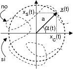
In questo tipo di modulazione, l'informazione contenuta nel messaggio x$ \left(\vphantom{ t}\right.$t$ \left.\vphantom{ t}\right)$ è impressa sulla portante modificandone la fase: x$ \left(\vphantom{ t}\right.$t$ \left.\vphantom{ t}\right)$ = acos$ \left(\vphantom{ \omega _{0}t+\alpha \left( t\right) }\right.$$ \omega_{0}^{}$t + $ \alpha$$ \left(\vphantom{ t}\right.$t$ \left.\vphantom{ t}\right)$ $ \left.\vphantom{ \omega _{0}t+\alpha \left( t\right) }\right)$.


0.250000
\resizebox* {0.25\columnwidth}{!}{\includegraphics{cap9/f9.14.ps}}

Si ottiene allora un inviluppo complesso
$\displaystyle \underline{x}$$\displaystyle \left(\vphantom{ t}\right.$t$\displaystyle \left.\vphantom{ t}\right)$ = 2x+$\displaystyle \left(\vphantom{ t}\right.$t$\displaystyle \left.\vphantom{ t}\right)$e-j$\scriptstyle \omega_{0}$t = 2 . a$\displaystyle {\textstyle\frac{1}{2}}$ej$\scriptstyle \omega_{0}$tej$\scriptstyle \alpha$$\scriptstyle \left(\vphantom{ t}\right.$t$\scriptstyle \left.\vphantom{ t}\right)$ . e-j$\scriptstyle \omega_{0}$t = aej$\scriptstyle \alpha$$\scriptstyle \left(\vphantom{ t}\right.$t$\scriptstyle \left.\vphantom{ t}\right)$  
  = a$\displaystyle \left[\vphantom{ \cos \alpha \left( t\right) +j\sin \alpha \left( t\right) }\right.$cos$\displaystyle \alpha$$\displaystyle \left(\vphantom{ t}\right.$t$\displaystyle \left.\vphantom{ t}\right)$ + jsin$\displaystyle \alpha$$\displaystyle \left(\vphantom{ t}\right.$t$\displaystyle \left.\vphantom{ t}\right)$ $\displaystyle \left.\vphantom{ \cos \alpha \left( t\right) +j\sin \alpha \left( t\right) }\right]$ = xc$\displaystyle \left(\vphantom{ t}\right.$t$\displaystyle \left.\vphantom{ t}\right)$ + jxs$\displaystyle \left(\vphantom{ t}\right.$t$\displaystyle \left.\vphantom{ t}\right)$  

Notiamo subito che, a differenza della AM, il modulo di $ \underline{x}$$ \left(\vphantom{ t}\right.$t$ \left.\vphantom{ t}\right)$ è rigorosamente costante e pari ad a, mentre la fase $ \alpha$$ \left(\vphantom{ t}\right.$t$ \left.\vphantom{ t}\right)$ varia continuamente.

\begin{floatingfigure}{0.450000\textwidth}
\vspace{0.3cm}
{\centering\begin{tabu...
...f}m\left( t\right) \)\\
\end{tabular}\par }
\vspace{0.3cm}
\end{floatingfigure}

Si è già mostrato come siano adottati 2 diversi tipi di legame tra messaggio m$ \left(\vphantom{ t}\right.$t$ \left.\vphantom{ t}\right)$ e fase dell'inviluppo complesso $ \alpha$$ \left(\vphantom{ t}\right.$t$ \left.\vphantom{ t}\right)$, indicati con PM (modulazione di fase) ed FM (modulazione di frequenza) che nella tabella a fianco. In questa compare la frequenza istantanea

fi$\displaystyle \left(\vphantom{ t}\right.$t$\displaystyle \left.\vphantom{ t}\right)$ = $\displaystyle {\frac{1}{2\pi }}$$\displaystyle {\frac{d}{dt}}$$\displaystyle \psi$$\displaystyle \left(\vphantom{ t}\right.$t$\displaystyle \left.\vphantom{ t}\right)$ = f0 + $\displaystyle {\frac{1}{2\pi }}$$\displaystyle {\frac{d}{dt}}$$\displaystyle \alpha$$\displaystyle \left(\vphantom{ t}\right.$t$\displaystyle \left.\vphantom{ t}\right)$

che è definita come la derivata della fase istantanea $ \psi$$ \left(\vphantom{ t}\right.$t$ \left.\vphantom{ t}\right)$ = 2$ \pi$f0t + $ \alpha$$ \left(\vphantom{ t}\right.$t$ \left.\vphantom{ t}\right)$. Le due alternative (PM e FM) sono analizzate assieme, in quanto reciprocamente intercambiabili qualora si effettui


- una PM con m$ \left(\vphantom{ t}\right.$t$ \left.\vphantom{ t}\right)$ pari all'integrale del messaggio informativo oppure

- una FM con m$ \left(\vphantom{ t}\right.$t$ \left.\vphantom{ t}\right)$ pari alla derivata del messaggio informativo.


Illustriamo subito alcune particolarità della modulazione angolare, prima di applicarci al problema della ricezione, ed alla determinazione della densità di potenza del segnale modulato.


Non linearità

La caratteristica fondamentale della modulazione angolare è che il segnale modulato ha una dipendenza da m$ \left(\vphantom{ t}\right.$t$ \left.\vphantom{ t}\right)$ fortemente non lineare, e pertanto lo spettro di densità di potenza $ \mathcal {P}$x$ \left(\vphantom{ f}\right.$f$ \left.\vphantom{ f}\right)$ del segnale modulato non può essere calcolato con le tecniche tradizionali. Infatti, l'inviluppo complesso di un segnale modulato di angolo può essere espresso9.22 come:

$\displaystyle \underline{x}$$\displaystyle \left(\vphantom{ t}\right.$t$\displaystyle \left.\vphantom{ t}\right)$ = aej$\scriptstyle \alpha$$\scriptstyle \left(\vphantom{ t}\right.$t$\scriptstyle \left.\vphantom{ t}\right)$ = a$\displaystyle \left[\vphantom{ 1+j\alpha \left( t\right) -\frac{\alpha ^{2}\left( t\right) }{2}-j\frac{\alpha ^{3}\left( t\right) }{3!}+...}\right.$1 + j$\displaystyle \alpha$$\displaystyle \left(\vphantom{ t}\right.$t$\displaystyle \left.\vphantom{ t}\right)$ - $\displaystyle {\frac{\alpha ^{2}\left( t\right) }{2}}$ - j$\displaystyle {\frac{\alpha ^{3}\left( t\right) }{3!}}$ + ...$\displaystyle \left.\vphantom{ 1+j\alpha \left( t\right) -\frac{\alpha ^{2}\left( t\right) }{2}-j\frac{\alpha ^{3}\left( t\right) }{3!}+...}\right]$

da cui risulta evidente che, anche se $ \mathcal {P}$$\scriptstyle \alpha$$ \left(\vphantom{ f}\right.$f$ \left.\vphantom{ f}\right)$ è esprimibile a partire da $ \mathcal {P}$M$ \left(\vphantom{ f}\right.$f$ \left.\vphantom{ f}\right)$, nulla può essere detto in generale per $ \mathcal {P}$$\scriptstyle \underline{x}$$ \left(\vphantom{ f}\right.$f$ \left.\vphantom{ f}\right)$ (e dunque per $ \mathcal {P}$x(f )= $ {\frac{1}{4}}$$ \mathcal {P}$$\scriptstyle \underline{x}$(f - f0) + $ {\frac{1}{4}}$$ \mathcal {P}$$\scriptstyle \underline{x}$(f + f0)). La presenza delle potenze dell'angolo $ \alpha$$ \left(\vphantom{ t}\right.$t$ \left.\vphantom{ t}\right)$ infatti, determina la non-applicabilità del principio di sovrapposizione degli effetti, ovvero, anche se sono noti i risultati della modulazione per due diversi messaggi x1$ \left(\vphantom{ t}\right.$t$ \left.\vphantom{ t}\right)$ = FM$ \left\{\vphantom{ m_{1}\left( t\right) }\right.$m1$ \left(\vphantom{ t}\right.$t$ \left.\vphantom{ t}\right)$ $ \left.\vphantom{ m_{1}\left( t\right) }\right\}$, x2$ \left(\vphantom{ t}\right.$t$ \left.\vphantom{ t}\right)$ = FM$ \left\{\vphantom{ m_{2}\left( t\right) }\right.$m2$ \left(\vphantom{ t}\right.$t$ \left.\vphantom{ t}\right)$ $ \left.\vphantom{ m_{2}\left( t\right) }\right\}$, il risultato ottenibile modulando la loro somma, non è quello della somma dei risultati individuali: FM $ \left\{\vphantom{ m_{_{1}}\left( t\right) +m_{2}\left( t\right) }\right.$m1$ \left(\vphantom{ t}\right.$t$ \left.\vphantom{ t}\right)$ + m2$ \left(\vphantom{ t}\right.$t$ \left.\vphantom{ t}\right)$ $ \left.\vphantom{ m_{_{1}}\left( t\right) +m_{2}\left( t\right) }\right\}$ $ \neq$ FM$ \left\{\vphantom{ m_{1}\left( t\right) }\right.$m1$ \left(\vphantom{ t}\right.$t$ \left.\vphantom{ t}\right)$ $ \left.\vphantom{ m_{1}\left( t\right) }\right\}$ + FM$ \left\{\vphantom{ m_{2}\left( t\right) }\right.$m2$ \left(\vphantom{ t}\right.$t$ \left.\vphantom{ t}\right)$ $ \left.\vphantom{ m_{2}\left( t\right) }\right\}$.

Ampiezza costante

La circostanza che $ \underline{x}$$ \left(\vphantom{ t}\right.$t$ \left.\vphantom{ t}\right)$ = aej$\scriptstyle \alpha$$\scriptstyle \left(\vphantom{ t}\right.$t$\scriptstyle \left.\vphantom{ t}\right)$ presenti un modulo costante pari ad a, indipendentemente dalle ampiezze del segnale modulante, è particolarmente utile, qualora per m$ \left(\vphantom{ t}\right.$t$ \left.\vphantom{ t}\right)$ siano da aspettarsi forti variazioni di dinamica. Questo è proprio il caso del segnale FDM, utilizzato per multiplare in frequenza piú canali telefonici. In questo caso infatti, non essendo noto a priori il numero di canali effettivamente impegnati, la potenza del segnale y$ \left(\vphantom{ t}\right.$t$ \left.\vphantom{ t}\right)$ = $ \sum_{n=1}^{N}$BLU$ \left\{\vphantom{ m_{n}\left( t\right) ,\: f_{n}}\right.$mn$ \left(\vphantom{ t}\right.$t$ \left.\vphantom{ t}\right)$fn$ \left.\vphantom{ m_{n}\left( t\right) ,\: f_{n}}\right\}$ ottenuto sommando i diversi canali (ognuno a modulazione BLU con una diversa portante) può variare di molto: allora, il segnale complessivo y$ \left(\vphantom{ t}\right.$t$ \left.\vphantom{ t}\right)$ viene applicato all'ingresso di un modulatore FM e trasmesso come tale.

Generazione di un segnale a modulazione angolare

Come anticipato, per effettuare una modulazione PM x$ \left(\vphantom{ t}\right.$t$ \left.\vphantom{ t}\right)$ = k$\scriptstyle \phi$m$ \left(\vphantom{ t}\right.$t$ \left.\vphantom{ t}\right)$ si può usare un modulatore FM, in cui $ \alpha$$ \left(\vphantom{ t}\right.$t$ \left.\vphantom{ t}\right)$ = 2$ \pi$kf$ \int^{t}_{-\infty }$m'($ \tau$)d$ \tau$, ponendo m'$ \left(\vphantom{ t}\right.$t$ \left.\vphantom{ t}\right)$ = $ {\frac{1}{2\pi }}$$ {\frac{k_{\phi }}{k_{f}}}$$ {\frac{d}{dt}}$m$ \left(\vphantom{ t}\right.$t$ \left.\vphantom{ t}\right)$. Pertanto, consideriamo nel seguito solo le operazioni di modulazione/demodulazione FM. Un metodo diretto di generare un segnale FM è quello di utilizzare un VCO (già introdotto in (9.2.1.3)), ossia un oscillatore controllato in tensione, che produce il segnale x$ \left(\vphantom{ t}\right.$t$ \left.\vphantom{ t}\right)$ = asin$ \left(\vphantom{ \omega _{0}t+2\pi k_{f}\int _{-\infty }^{t}m(\tau )d\tau }\right.$$ \omega_{0}^{}$t + 2$ \pi$kf$ \int_{-\infty }^{t}$m($ \tau$)d$ \tau$ $ \left.\vphantom{ \omega _{0}t+2\pi k_{f}\int _{-\infty }^{t}m(\tau )d\tau }\right)$, e dunque realizza proprio la funzione desiderata. Un secondo metodo verrà illustrato per un caso particolare in appendice 9.4.5. Infine, è sempre valido il modulatore in fase e quadratura, in cui si pone xc$ \left(\vphantom{ t}\right.$t$ \left.\vphantom{ t}\right)$ = cos$ \alpha$$ \left(\vphantom{ t}\right.$t$ \left.\vphantom{ t}\right)$ e xs$ \left(\vphantom{ t}\right.$t$ \left.\vphantom{ t}\right)$ = sin$ \alpha$$ \left(\vphantom{ t}\right.$t$ \left.\vphantom{ t}\right)$.


Sottosezioni
next up previous contents index
Avanti: Ricezione di un segnale a modulazione Su: Modulazione per Segnali Analogici Indietro: Frequenze immagine   Indice   Indice analitico
alef@infocom.uniroma1.it
2001-06-01